- 您现在的位置:买卖IC网 > Sheet目录350 > PCA9632DP2,118 (NXP Semiconductors)IC LED DRIVER RGBA 10-TSSOP
�� �
�
�NXP� Semiconductors�
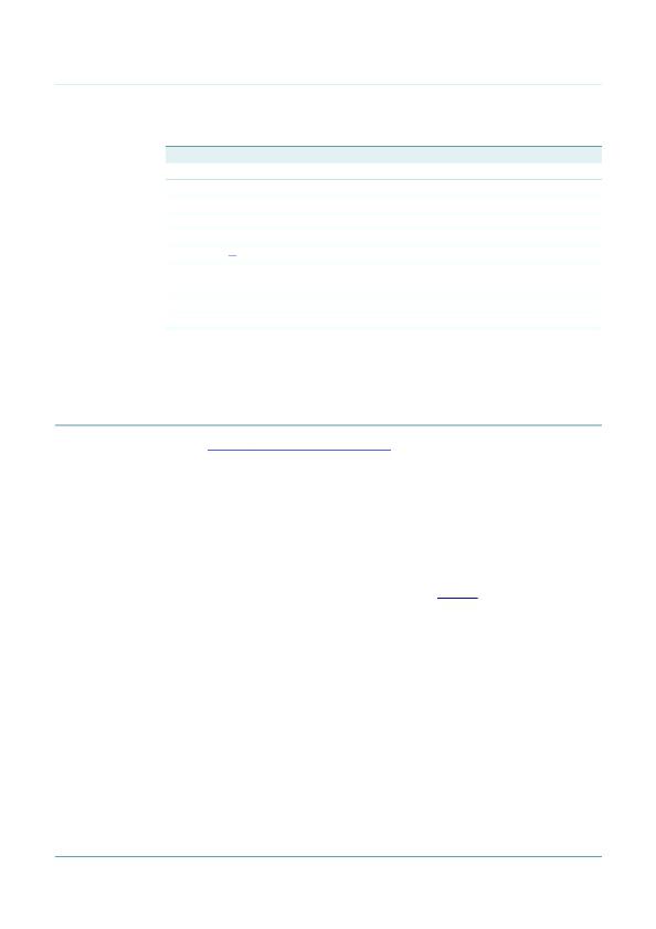
�Table� 3.�
�PCA9632�
�4-bit� Fm+� I� 2� C-bus� low� power� LED� driver�
�Pin� description� for� TSSOP10� and� HVSON10�
�Symbol�
�LED0�
�LED1�
�LED2�
�LED3�
�A0�
�V� SS�
�A1�
�SCL�
�SDA�
�V� DD�
�Pin�
�1�
�2�
�3�
�4�
�5�
�6� [1]�
�7�
�8�
�9�
�10�
�Type�
�O�
�O�
�O�
�O�
�I�
�power� supply�
�I�
�I�
�I/O�
�power� supply�
�Description�
�LED� driver� 0�
�LED� driver� 1�
�LED� driver� 2�
�LED� driver� 3�
�address� input� 0�
�supply� ground�
�address� input� 1�
�serial� clock� line�
�serial� data� line�
�supply� voltage�
�[1]�
�HVSON10� package� die� supply� ground� is� connected� to� both� the� V� SS� pin� and� the� exposed� center� pad.� The�
�V� SS� pin� must� be� connected� to� supply� ground� for� proper� device� operation.� For� enhanced� thermal,� electrical,�
�and� board-level� performance,� the� exposed� pad� needs� to� be� soldered� to� the� board� using� a� corresponding�
�thermal� pad� on� the� board,� and� for� proper� heat� conduction� through� the� board� thermal� vias� need� to� be�
�incorporated� in� the� PCB� in� the� thermal� pad� region.�
�7.� Functional� description�
�Refer� to� Figure� 1� “� Block diagram of PCA9632� ”� .�
�7.1� Device� addresses�
�Following� a� START� condition,� the� bus� master� must� output� the� address� of� the� slave� it� is�
�accessing.�
�There� are� a� maximum� of� 4� possible� programmable� addresses� using� the� 2� hardware�
�address� pins� for� the� 10-pin� version� and� just� one� fixed� address� for� the� 8-pin� version.�
�7.1.1� Regular� I� 2� C-bus� slave� address�
�The� I� 2� C-bus� slave� address� of� the� PCA9632� is� shown� in� Figure 6� .� To� conserve� power,� no�
�internal� pull-up� resistors� are� incorporated� on� the� hardware� selectable� address� pins� and�
�they� must� be� pulled� HIGH� or� LOW� (10-pin� versions� only).�
�Remark:� Using� reserved� I� 2� C-bus� addresses� will� interfere� with� other� devices,� but� only� if�
�the� devices� are� on� the� bus� and/or� the� bus� will� be� open� to� other� I� 2� C-bus� systems� at� some�
�later� date.� In� a� closed� system� where� the� designer� controls� the� address� assignment� these�
�addresses� can� be� used� since� the� PCA9632� treats� them� like� any� other� address.� The�
�LED� All� Call,� Software� Reset� and� PCA9564� or� PCA9665� slave� address� (if� on� the� bus)� can�
�never� be� used� for� individual� device� addresses.�
�?� PCA9632� LED� All� Call� address� (1110� 000)� or� Software� Reset� (0000� 0110)� which� are�
�active� on� start-up�
�?� PCA9564� (0000� 000)� or� PCA9665� (1110� 000)� slave� address� which� is� active� on�
�start-up�
�?� ‘reserved� for� future� use’� I� 2� C-bus� addresses� (0000� 011,� 1111� 1XX)�
�?� slave� devices� that� use� the� 10-bit� addressing� scheme� (1111� 0XX)�
�PCA9632�
�Product� data� sheet�
�All� information� provided� in� this� document� is� subject� to� legal� disclaimers.�
�Rev.� 5� —� 27� July� 2011�
�?� NXP� B.V.� 2011.� All� rights� reserved.�
�6� of� 39�
�发布紧急采购,3分钟左右您将得到回复。
相关PDF资料
PCA9633BS,118
IC LED DRIVER RGBA 16-HVQFN
PCA9634D,118
IC LED DRIVER RGBA 20-SOIC
PCA9635PW/S911,118
IC LED DRIVER RGBA 28-TSSOP
PCA9685PW,118
IC LED DRIVER RGBA 28-TSSOP
PCA9922PW,118
IC LED DRIVER LINEAR 16-TSSOP
PCA9955TW,118
IC LED DRVR CONST CURR
PCF85102C-2P/03,11
IC EEPROM 2KBIT 100KHZ 8DIP
PCF85103C-2T/00,11
IC EEPROM 2KBIT 100KHZ 8SOIC
相关代理商/技术参数
PCA9632DP2118
制造商:NXP Semiconductors 功能描述:IC LED DRVR TSSOP
PCA9632DP2-T
功能描述:LED照明驱动器 4-BIT FM+I2C-BUS LOW POWER LED RoHS:否 制造商:STMicroelectronics 输入电压:11.5 V to 23 V 工作频率: 最大电源电流:1.7 mA 输出电流: 最大工作温度: 安装风格:SMD/SMT 封装 / 箱体:SO-16N
PCA9632TK,118
功能描述:LED照明驱动器 4-BIT FM+I2C-BUS RoHS:否 制造商:STMicroelectronics 输入电压:11.5 V to 23 V 工作频率: 最大电源电流:1.7 mA 输出电流: 最大工作温度: 安装风格:SMD/SMT 封装 / 箱体:SO-16N
PCA9632TK2,118
功能描述:LED照明驱动器 4-BIT FM+I2C-BUS RoHS:否 制造商:STMicroelectronics 输入电压:11.5 V to 23 V 工作频率: 最大电源电流:1.7 mA 输出电流: 最大工作温度: 安装风格:SMD/SMT 封装 / 箱体:SO-16N
PCA9632TK2-T
功能描述:LED照明驱动器 4-BIT FM+I2C-BUS LOW POWER LED RoHS:否 制造商:STMicroelectronics 输入电压:11.5 V to 23 V 工作频率: 最大电源电流:1.7 mA 输出电流: 最大工作温度: 安装风格:SMD/SMT 封装 / 箱体:SO-16N
PCA9632TK-T
功能描述:LED照明驱动器 4-BIT FM+I2C-BUS LOW POWER LED RoHS:否 制造商:STMicroelectronics 输入电压:11.5 V to 23 V 工作频率: 最大电源电流:1.7 mA 输出电流: 最大工作温度: 安装风格:SMD/SMT 封装 / 箱体:SO-16N
PCA9633BS,118
功能描述:LED照明驱动器 4BIT I2C FM+ TP LED RoHS:否 制造商:STMicroelectronics 输入电压:11.5 V to 23 V 工作频率: 最大电源电流:1.7 mA 输出电流: 最大工作温度: 安装风格:SMD/SMT 封装 / 箱体:SO-16N
PCA9633BS-T
功能描述:LED照明驱动器 4BIT I2C FM+ TP LED CON RST OE RoHS:否 制造商:STMicroelectronics 输入电压:11.5 V to 23 V 工作频率: 最大电源电流:1.7 mA 输出电流: 最大工作温度: 安装风格:SMD/SMT 封装 / 箱体:SO-16N